Showing posts with label Computer Organization and Architecture. Show all posts

Program for the Basic Computer to move a block of data from one location to another using SUBROUTINE

Suppose, 10 data (16-bit) stored from 220H memory address (12-bit) must be transferred to another block starting from 250H memory address. For this, each data should be loaded to accumulator first and then stored to destination address. Then, source address and destination address should be incremented. Assembly program will be the following:

X, BSA TRN
/TRN is a subroutine to transfer data
BSA SRC
/SRC is a subroutine for source address management
BSA DST
/DST is a subroutine for destination address management
ISZ CTR
/CTR is counter for 10 data
BUN X
HLT

TRN, HEX 0
LDA A I
STA B I
BUN TRN I

SRC, HEX 0
LDA A
INC
STA A
BUN SRC I

DST, HEX 0
LDA B
INC
STA B
BUN DST I

A, HEX 220
B, HEX 250
CTR, DEC -10
END

Assembly Program for the Basic Computer for the following series

12 + 22 + 32 + 42 + …… up to 10 terms 

XYZ, LDA T1
CMA
INC
STA T2
CLA
ABC, ADD T1
ISZ T2
BUN ABC
ADD S
STA S
BSA PQR
ISZ C
BUN XYZ
HLT

PQR, HEX 0
LDA T1
INC
STA T1
BUN PQR I

T1, DEC 1
T2, DEC 0
S, DEC 0
C, DEC -10
END

Assembly Program for the Basic Computer designed by Morris Mano

Q. WAP for Basic Computer to add 10 numbers located from the address 100H, then store the result at 200H address.

ADR, HEX 100
CTR, DEC -10
        CLA
REP,  ADD ADR I
         STA SUM
         LDA ADR
         INC
         STA ADR
         LDA SUM
         ISZ CTR
         BUN REP
         HLT
ORG 200
SUM, HEX 0
END

1*2 + 3*4 + 5*6 + ...... up to 10 terms in the Basic Computer

XYZ, LDA T2
CMA
INC
STA T3
CLA
ABC, ADD T1
ISZ T3
BUN ABC
ADD SUM
STA SUM
BSA PQR
ISZ CTR
BUN XYZ
HLT

PQR, HEX 0
LDA T1
INC
INC
STA T1
LDA T2
INC
INC
STA T2
BUN PQR I

T1, DEC 1
T2, DEC 2
T3, DEC 0
SUM, DEC 0
CTR, DEC -10
END

Sum of Natural Numbers 1+2+3+........+9 for the Basic Computer

/1+2+3+......+9

REP, LDA SUM
ADD TRM
STA SUM
LDA TRM
INC
STA TRM
ISZ CTR
BUN REP
HLT
TRM, DEC 1
SUM, DEC 0
CTR, DEC -9
END

In C Programming,
int s=0;
for(int t=1;t<=9;t++)
    s=s+t;

Like in this, we have to load the sum (s) first, add it with first term (t) and store in the sum (s). Then, we have to update the term (t) and add it again until the counter hits zero (0). The term itself is counter here

The Assembler for the Basic Computer

An assembler is a program that accepts a symbolic language program and produces its binary machine language equivalent. The input symbolic program is called the source program and the resulting binary program is called the object program. The assembler is a program that operates on character strings and produces an equivalent binary interpretation.

Representation of Symbolic Program in Memory

  • The user types the symbolic program on a terminal. A loader program is used to input the characters of the symbolic program into memory.
  • In the basic computer, each character is represented by an 8-bit code. The high-order bit is always 0 and the other seven bits are as specified by ASCII.
Table: ASCII code (in Hexadecimal code) for characters
  • The code for CR is produced when the return key is depressed. This causes the “carriage” to return to its position to start typing a new line. The assembler recognizes a CR code as the end of a line of code.
  • A line of code is stored in consecutive memory locations with two characters in each location since a memory word has a capacity of 16 bits.
  • A label symbol is terminated with a comma. Operation and address symbols are terminated with a space and the end of the line is recognized by the CR code.
  • For example, the following line of code:
PL3, LDA SUB I
Fig: Computer Representation of the Line of Code: PL3, LDA SUB I
  • Each symbol is terminated by the code for space (20) except for the last symbol, which is terminated by the code of carriage return (OD).
  • If the line of code has a comment, the assembler recognizes it by the code for a slash (2F). The assembler neglects all characters in the comment field and keeps checking for a CR code. When this code is encountered, it replaces the space code after the last symbol in the line of code.
  • This input is scanned by the assembler twice to produce the equivalent binary program. The binary program constitutes the output generated by the assembler.

First Pass

  • A two pass assembler scans the entire symbolic program twice. During the first pass, it generates a table that correlates all user defined address symbols with their binary equivalent value.
  • The binary translation is done during the second pass.
  • To keep track of the location of instructions, the assembler uses a memory word called a location counter (abbreviated LC). The content of LC stores the value of the memory location assigned to the instruction or operand presently being processed.

Assembly Language for the Basic Computer

The basic unit of an assembly language program is a line of code. The specific language is defined by a set of rules that specify the symbols that can be used and how they may be combined to form a line of code.

Rules of the Language
  • Each line of an assembly language program is arranged in three columns called fields which specify the following information:
  1. The label field may be empty or it may specify a symbolic address.
  2. The instruction field specifies a machine instruction or a pseudo instruction.
  3. The comment field may be empty or it may include a comment.
  • A symbolic address, which is terminated by a comma, consists of one, two, or three, but not more than three alphanumeric characters. The first character must be a letter; the next two may be letters or numerals. A symbolic address in the instruction field specifies the memory location of an operand.
  • The instruction field in an assembly language program may specify one of the following items:
  1. A memory reference instruction (MRI)
          E.g. ADD OPR
          ADD PTR I
      2. A register reference or input-output instruction (non MRI)
          E.g. CLA
      3. A pseudo instruction with or without an operand
          E.g. ORG 0
          END
  • A MRI occupies two or three symbols separated by spaces. The first must be a three letter symbol defining an MRI operation code, the second is symbolic address and the third symbol, which may or may not be present, is the letter I. If I is missing, it denotes direct address instruction. If I is present, it denotes indirect address instruction.
  • A non MRI is defined as an instruction that does not have an address part. It consists of only operation code.
  • A pseudo instruction is not a machine instruction but rather an instruction to the assembler giving information about some phase of the translation.
Definition of Pseudo instructions
  • A line of code may or may not have a comment, but if it has, it must be preceded by a slash for the assembler to recognize the beginning of a comment field. Comments are inserted for explanation purposes only and are neglected during the binary translation process.
  • Example:
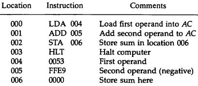
Assembly Language Program to Subtract Two Numbers

Programming the Basic Computer

Assembly Language Program to Add Two Numbers

 Program with Symbolic Operation Codes

Hexadecimal Program to Add Two Numbers

Basic Computer Organization and Design

Complete Computer Description

Flowchart

This is the final flowchart of the instruction cycle including interrupt cycle for the basic computer.


Basic Computer Organization and Design

Program Interrupt

  • Input and Output interactions with electromechanical peripheral devices require huge processing times compared with CPU processing times
  • I/O (milliseconds) versus CPU (nano/micro-seconds)
  • Interrupts permit other CPU instructions to execute while waiting for I/O to complete
  • The I/O interface, instead of the CPU, monitors the I/O device.
  • When the interface founds that the I/O device is ready for data transfer, it generates an interrupt request to the CPU.
  • Upon detecting an interrupt, the CPU stops momentarily the task it is doing, branches to the service routine to process the data transfer, and then returns to the task it was performing.
Scenario3: consider a computer which completes instruction cycle in 1µs. Assume I/O device that can transfer information at the maximum rate of 10 characters/sec. Equivalently, one character every 100000µs. Two instructions are executed when computer checks the flag bit and decides not to transfer information. Which means computer will check the flag 50000 times between each transfer. Computer is wasting time while checking the flag instead of doing some useful processing task.

IEN (Interrupt-enable flip-flop)
  • can be set and cleared by instructions
  • When cleared, the computer cannot be interrupted

Interrupt Cycle

This is a hardware implementation of a branch and save return address operation.

Fig: flowchart of interrupt cycle

Fig: Demonstration of interrupt cycle
  • At the beginning of the instruction cycle, the instruction that is read from memory is in address 1. 
  • At memory address 1, the programmer must store a branch instruction that sends the control to an interrupt service routine 
  • The instruction that returns the control to the original program is "indirect BUN 0" 
Register transfer operations in interrupt cycle
Register Transfer Statements for Interrupt Cycle
    - R F/F ← 1 if IEN (FGI + FGO) T0’T1’T2’ ↔ T0’T1’T2’ (IEN) (FGI + FGO): R ← 1
  • The fetch and decode phases of the instruction cycle must be modified: Replace T0, T1, T2 with R'T0, R'T1, R'T2
  • The interrupt cycle : 
RT0: AR ← 0, TR ← PC
RT1: M[AR] ← TR, PC ← 0
RT2: PC ← PC + 1, IEN ← 0, R ← 0, SC ← 0


Basic Computer Organization and Design

Input-Output Configuration

The terminal sends and receives serial information. Each quantity of information has 8 bits of an alphanumeric code. The serial information from the keyboard is shifted into the input register INPR. The serial information for the printer is stored in the output register OUTR. These two registers communicate with a communication interface serially and with the AC in parallel. The input—output configuration is shown in figure. The transmitter interface receives serial information from the keyboard and transmits it to INPR. The receiver interface receives information from OUTR and sends it to the printer serially. 
Fig: Input-Output Configuration

Scenario1: when a key is struck in the keyboard, an 8-bit alphanumeric code is shifted into INPR and the input flag FGI is set to 1. As long as the flag is set, the information in INPR cannot be changed by striking another key. The control checks the flag bit, if 1, contents of INPR is transferred in parallel to AC and FGI is cleared to 0. Once the flag is cleared, new information can be shifted into INPR by striking another key.

Scenario2: OUTR works similarly but the direction of information flow is reversed. Initially FGO is set to 1. The computer checks the flag bit; if it is 1, the information is transferred in parallel to OUTR and FGO is cleared to 0. The output device accepts the coded information, prints the corresponding character and when operation is completed, it sets FGO to 1.

Basic Computer Organization and Design

Instruction Cycle

  • Processing required for complete execution of an instruction is called instruction cycle.
  • In Basic Computer, a machine instruction is executed in the following cycle:
1. Fetch an instruction from memory
2. Decode the instruction
3. Read the effective address from memory if the instruction has an indirect address
4. Execute the instruction

Upon the completion of step 4, control goes back to step 1 to fetch, decode and execute the next instruction. This process is continued indefinitely until HALT instruction is encountered.

Fetch and Decode
  • Sequence of steps required for fetching instruction from memory to CPU internal register is known as fetch cycle.
  • For fetching and decoding, the steps are:
i) Initially, PC holds the address of next instruction to fetch. With timing signal T0, address pointed by PC is transferred to the AR.
ii) The processor fetches instruction to IR from memory location referenced by AR and increment PC for next instruction. This happens with timing signal T1.
iii) Processor interprets instruction and performs required action i.e. decoding during time period T2. 
Fig: Flowchart of Instruction Cycle
  • Then, among decoded, D7 determines which type of instruction.
i) If D7 = 1, it will be either register-reference or input-output instruction.
    a) If I = 1, input-output instruction is executed during T3.
    b) If I = 0, register-reference instruction is executed during T3.
ii) If D7 = 0, it will be memory-reference instruction.
    a) If I = 1, indirect addressing mode instruction during T3.
    b) If I = 0, direct addressing mode instruction during T3.
  • The SC is reset after executing each instruction.

Basic Computer Organization and Design

Timing and Control Unit

Control Unit

Control unit (CU) of a processor translates from machine instructions to the control signals for the microoperations that implement them.
The block diagram of a hardwired control unit is shown below. It consists of two decoders, a sequence counter, and a number of control logic gates.

Fig: Control unit of a basic computer

Mechanism:
  • An instruction read from memory is placed in the instruction resister (IR) where it is decoded into three parts: I bit, operation code and bits 0 through 11.
  • The operation code bit is decoded with 3 x 8 decoder producing 8 outputs D0 through D7.
  • Bit 15 of the instruction is transferred to a flip-flop I.
  • And operand bits are applied to control logic gates.
  • The 16 outputs of 4-bit sequence counter (SC) are decoded into 16 timing signals T0 through T15. 
This means instruction cycle of basic computer cannot take more than 16.


Timing Signals

  • Generated by 4-bit sequence counter and 4x16 decoder.
  • The SC can be incremented or cleared. 
  • Example: T0, T1, T2, T3, T4, T0, T1 . . . 
Assume: At time T4, SC is cleared to 0 if decoder output D3 is active: D3T4: SC <¬ 0

Basic Computer Organization and Design

Below is the complete operation that takes place during the instruction:

Fig: Memory-Reference Instructions

Branch and Save Return Address (BSA)
D5T4: M[AR] <— PC, AR <— AR + 1
D5T5: PC <— AR, SC <— 0

For this example:
M[135] <— 21, AR <— 135 + 1 
PC <— 136 

Fig: Register-Reference Instructions

Basic Computer Organization and Design

Instruction Formats and their Execution

  • The instruction length of basic computer is 16-bit.
  • 16-bit instruction of basic computer has three fields:
Mode
Op-code
Operand (Address)

i) Mode field
  • MSB (bit 15) of the 16-bit instruction.
  • Value 0 = direct addressing, value 1 = indirect addressing mode.
ii) Op-code field
  • Defines what operation to be performed.
  • Contains 3 bits (bits 14-12)
iii) Operand (Address) field
  • Contains 12 bits (bits 11-0)
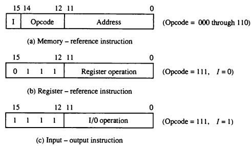
The basic computer has 3 instruction code formats. Type of the instruction is recognized by the computer control from 4-bit positions 12 through 15 of the instruction.
i) Memory-Reference Instructions
ii) Register-Reference Instructions
iii) Input-Output Instructions

Basic Computer Organization and Design

Basic Computer Registers

Computer instructions are normally stored in the consecutive memory locations and are executed sequentially one at a time. Thus computer needs processor registers for manipulating data and holding memory address which are shown in the following table:
  • Since the memory in the Basic Computer only has 4096 (=212) locations, PC and AR only needs 12 bits.
  • Since the word size of Basic Computer only has 16 bit, the DR, AC, IR and TR needs 16 bits. The Basic Computer uses a very simple model of input/output (I/O) operations.
  • Input devices are considered to send 8 bits of character data to the processor
  • The processor can send 8 bits of character data to output devices
  • The Input Register (INPR) holds an 8-bit character gotten from an input device and the Output Register (OUTR) holds an 8-bit character to be sent to an output device.


Common Bus System


  • The basic computer has eight registers, a memory unit, and a control unit.
  • These registers, memory and control unit are connected using a path (bus) so that information can be transferred to each other.

Basic Computer Organization and Design

Introduction to Basic Computer

We introduce here a basic computer whose operation can be specified by the resister transfer statements. Internal organization of the computer is defined by the sequence of microoperations it performs on data stored in its resisters. Every different processor type has its own design (different registers, buses, microoperations, machine instructions, etc). Modern processor is a very complex device. It contains:
– Many registers
– Multiple arithmetic units, for both integer and floating point calculations
– The ability to pipeline several consecutive instructions for execution speedup.
However, to understand how processors work, we will start with a simplified processor model. M. Morris Mano introduces a simple processor model; he calls it a “Basic Computer”. The Basic Computer has two components, a processor and memory.
  • The memory has 4096 words in it
        – 4096 = 212, so it takes 12 bits to select an address in memory
  • Each word is 16 bits long

Stored Program Organization

  • The program (instruction) as well as data (operand) is stored in the same memory.

Instruction Format 

A computer instruction is often divided into two parts:

Assembly Program for Basic Computer :: Subtract two numbers and Store the result in memory with CONDITION

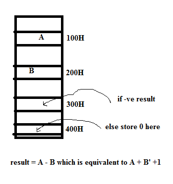
Q. Write an assembly program for Basic Computer (designed by M. Morris Mano) to subtract two numbers located at 100H and 200H. Then, store the result in 300H if the result is negative, else store zero (0) in 400H.


LDA 200H /AC<-M[200H]
CMA
ADD 100H /AC<-AC+M[100H]
SPA /skip if AC +ve
STA 300H /M[300H]<-AC
SNA /skip if AC -ve
BSA XYZ
HLT /stop i.e. S<-0

XYZ, DEC 0
CLA
STA 400H /M[400H]<-AC
BUN XYZ I


Assembly Program for Basic Computer :: Add two numbers and Store the result in memory

Q. Write an assembly program for Basic Computer (designed by M. Morris Mano) to add two numbers located at 100H and 200H. Then, store the result in 300H if the result is positive, else store in 400H.

LDA 100H        /AC<-M[100H]
ADD 200H        /AC<-AC+M[200H]
SNA                  /skip if AC -ve
STA 300H        /M[300H]<-AC
SPA                  /skip if AC +ve
STA 400H        /M[400H]<-AC
HLT                 /stop i.e. S<-0

Assembly Program for Basic Computer :: Input and Output

Q. Write an assembly program for Basic Computer (designed by M. Morris Mano) to input and display two numbers.

CTR, DEC -2        /counter for two numbers
LP1, SKI        /skip (i.e. PC<-PC+1) if FGI=1
BUN LP1
INP
LP2, SKO        /skip (i.e. PC<-PC+1) if FGO=1
BUN LP2
OUT
ISZ CTR        /increment CTR and skip if CTR=0
BUN LP1